Setting the stage for TRILL, rethinking data center switching

As data centers become increasingly dynamic and dense with virtualization - how the classic Ethernet switching design adopts to these new models and scales becomes an important and challenging question. Virtualization and cloud based services says that any workload can exist anywhere, at anytime, on demand, and move to any location without disruption. This is a major paradigm shift from the old days where a “Server” and the application it supported had a very static location in the network. When the application has a static location you can build walls around it in a very structured manner with minimal trade-offs. In the old “static” Data Center, you could for example provide Layer 3 routing boundaries at the server edge for the very good reasons of robust scalability, minimal or no Spanning Tree, and active/active router-like link load balancing and fast convergence. In today’s dynamic Data Center, the imposition of Layer 3 boundaries no longer works.
The next generation dynamic Data Center requires a pervasive Layer 2 deployment enabling the aforementioned fluid mobility of application workloads. Any VLAN, on any switch, on any port, at anytime. As as result, switch makers (in order to remain viable in the data center) must be geared towards enabling pervasive Layer 2 data center fabrics in a manner that is highly scalable (agile), robust, maximizes bandwidth (resources), with plug & play simplicity.
One major step forward in designing next generation data centers is the promising technology which is currently defined in RFC 5556 named [TRILL (Transparent Interconnection of Lots of Links)](http://en.wikipedia.org/wiki/TRILL_(Computer_Networking). Some switch vendors (such as Cisco) may initially offer the capabilities found in TRILL with additional enhancements as a proprietary system. Therefore, for the time being I am going to use the word TRILL in a generic sense. And where a capability is discussed that is a unique enhancement offered by Cisco (or any other vendor) I will simply cite that with an , such as TRILL.
Before we discuss TRILL in great detail I think it’s important first to take a step back and “Set the stage” a little by revisiting the classic Ethernet design principles currently in use today, understanding both the strengths and challenges. Then we’ll look at some alternative approaches that attempt to address these challenges, and where they fall short. As we go through the various areas I will point out where TRILL can make design improvements. Once we have this basis of understanding we will be ready to understand the value of TRILL with more detail in subsequent discussions. Sound cool? Great!
Revisiting Classic Ethernet. What works? What needs improvement?
A fundamental underpinning of Ethernet is the “Plug & Play” simplicity that in no small measure has contributed to the overall tremendous success of Ethernet. When you connect Ethernet switches together they can auto discover the topology and automatically learn about each host’s location on the network, with little to no configuration. Any future evolution of Ethernet must retain this fundamental “Plug & Play” characteristic to be successful. The key enabler of this Plug & Play capability is Flooding Behavior.
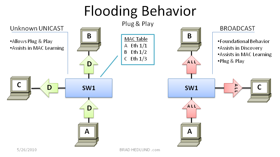
Figure 1 above shows two simple examples of Ethernet flooding behavior. On the left, if an Ethernet switch receives a Unicast frame with a destination that it doesn’t know about, it simply floods that frame out on all ports. This behavior is called Unicast Flooding and it insures that the destination host receives the frame so long as it is connected to the network, without any special configuration (Plug & Play).
The other flooding behavior shown on the right (Figure 1 above) is a Broadcast message that is intended for all hosts on the network. When the Ethernet switch receives a broadcast frame, it will simply do as told and send a copy of that frame to all active ports. Broadcast messages are tremendously useful for hosts seeking to dynamically discover other hosts connected to the network without any special configuration (Plug & Play).
This default flooding behavior of Ethernet is fundamental to its greatest virtue, Plug & Play simplicity. However, this same flooding behavior also creates design challenges that we will discuss shortly.
The flooding of unknown unicast and broadcasts frames also allows for Plug & Play learning of the all the hosts and their location in the network, without any special configuration. Once the location of a host is known, all subsequent traffic to that host will be sent only to the ports leading to the host. I will refer to this type of traffic as Known Unicast traffic.
The process of automatically discovering a hosts location on the network is called MAC Learning:

Figure 2 above shows a simple example of the automatic MAC Learning process. Every time an Ethernet switch receives a frame on a port it looks at the source MAC address of the received frame and records the port and source MAC on which it received the frame in its forwarding table, aka MAC Table. That’s it! Its that simple. Any future frames received that are destined to the learned MAC address will be directed only to the port on which it was learned. This process is more specifically described as Source MAC Learning, because only the Source MAC address is examined upon receiving a frame.
Because of the flooding behavior discussed earlier, the Ethernet switch can quickly learn the location of all hosts on the network. Anytime a host sends a broadcast message it will be received by all Ethernet switches where the source MAC address of the sending station will be recorded and learned, as shown in Figure 2.
There is a peculiar side effect to Source MAC Learning: All Ethernet switches will inevitably learn about all hosts, needed or not. For example, in Figure 2 above, Host C and Host D are communicating on Switch 4. The Source MAC learning process was useful in establishing a Known Unicast conversation for these two hosts using Switch 4. However, despite the fact that Host A and Host B are not using Switch 4 for any conversations, Switch 4 has still populated its MAC Table with entries for Host A and Host B.
“Whats wrong with that?” you ask? Well, in the old “static” Data Center with small Layer 2 domains this was never a concern. Now imagine this inefficient behavior on a much larger scale in the dynamic Data Center with thousands of virtual hosts in a pervasive Layer 2 domain. The unfortunate side effect is that you will have many unnecessary entries in every Ethernet switch. And each one of these unnecessary entries consumes valuable space in the MAC Table where there is a limited number of entries available. A typical data center class Ethernet switch might support 16,000 MAC entries. Again, not a problem in the “static” Data Center. However this poses a scalability challenge in the virtualization dense dynamic Data Center. Is this something that can be improved while maintaining the Plug & Play auto learning behavior? The answer is, Yes, this is an area enhanced by TRILL*
Now lets move on to the design challenge with flooding behavior I mentioned earlier. Remember, the flooding behavior of Ethernet is fundamental to achieving Plug & Play capabilities, so we cant get rid of it, we need it. The challenge with flooding is there is no mechanism to know when a flooded frame (such as a Broadcast) has already made its way through the network. Every time a Broadcast or Unknown Unicast frame is received it is immediately flooded out on all ports, no questions asked, even if this is the same frame returning to the switch from a previous flood, there is no way to know. This can become a real problem when you have multiple paths from one switch to another.
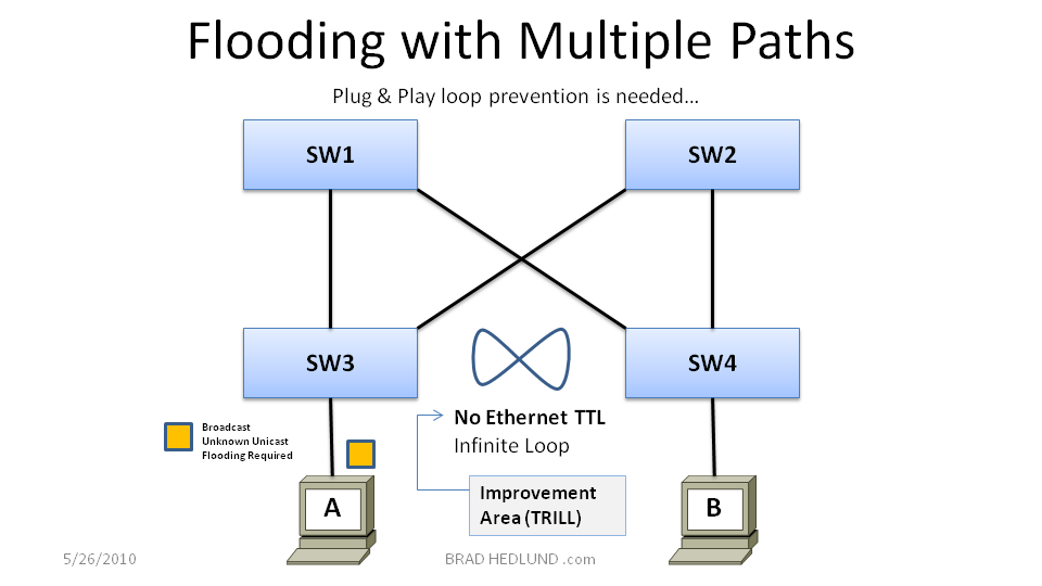
In Figure 3 above, Host A sends a Broadcast or Unknown Unicast frame into Switch 3 which is then flooded on the links connecting to Switch 1 and Switch 2. Once received, Switch 1 & 2 will also flood the frame on all of their ports, and so on. Switch 3 ultimately receives the original frame again and the same process repeats. Unlike an IP packet that increments a TTL field (time to live) with every hop, there is no such TTL field or other mechanism in an Ethernet frame that provides information about the frames age or history on the network. As a result, the flooding loop repeats infinitely with every new broadcast. It doesn’t take long for the loop to have catastrophic effects on the network (within seconds). Can Ethernet be enhanced with a TTL field just like IP to limit the scope of unwanted loops? The answer is, Yes, this is an area enhanced by TRILL.
This looping challenge above led to the development of a Plug & Play mechanism in Ethernet to detect and prevent loops called Spanning Tree Protocol (STP).
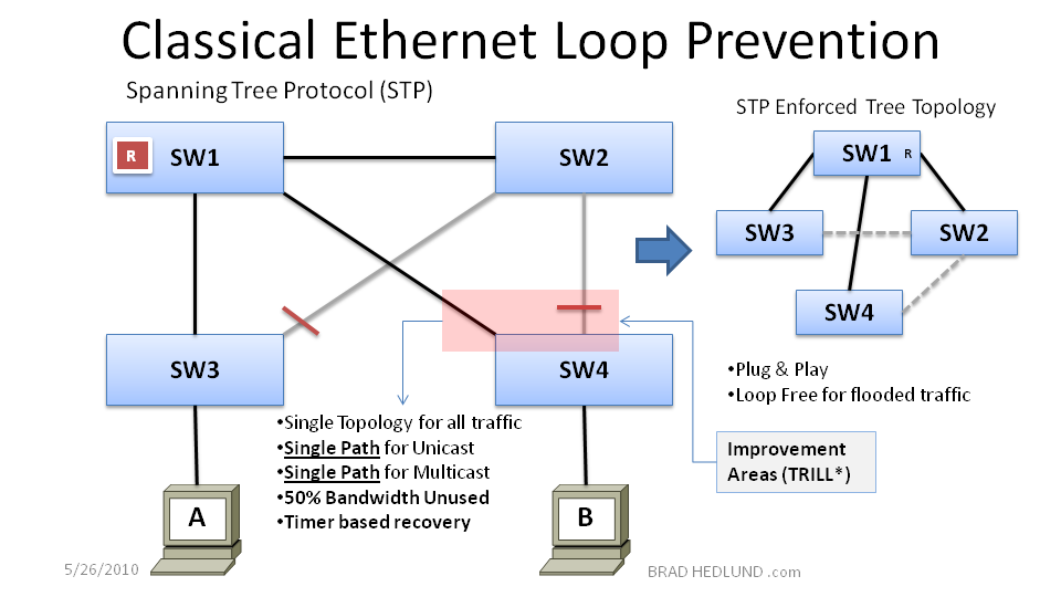
In Figure 4 above, the Ethernet switches have auto discovered a redundant path in the network using STP and placed certain interfaces in a “Blocking” state to prevent the disastrous infinite looping of flooded frames. The Spanning Tree protocol is Plug & Play, requiring no configuration work, and because it prevents the disastrous loops that allow flooding to work properly in a network with redundant paths, you could argue that STP (even with it’s infamous reputation) is THE reason why Ethernet is so successful today as a mission critical data center network technology. Now, truth be told, STP does require some configuration tuning if you want to have precise control over which links are placed into a “Blocking” state. Such as in Figure 4 above, whereby defining Switch 1 as the “Root” bridge we can influence redundant links from Switch 3 & 4 to block loops and provide a balance of bandwidth available to hosts on either Switch 3 or Switch 4, each switch having 50% of its bandwidth available for hosts.
There is an unfortunate side effect with STP. Remember, it is the Broadcast and Unknown Unicast frames flooding and looping the network that cause the catastrophic effects which we must correct with STP. The non-flooded Known Unicast traffic is not causing the problem. However, when STP blocks a path to close a loop, it is in fact punishing bandwidth availability for ALL traffic, including the Known Unicast traffic, the significant majority of all traffic on the network! Thats not fair! Can we enhance Ethernet to correct this unfair side effect? The answer is, Yes, this an area enhanced by TRILL.
Given that STP creates a single loop free forwarding topology for all traffic, flooded or non-flooded, it became increasingly import to build loop free topologies while maintaining multiple paths, maximizing bandwidth, without STP blocking any of those valuable paths, especially in 10GE data center networks. In order for STP to not block any of the paths we must first show STP a loop free topology from the start.
Building loop free topologies with multiple paths can be accomplished with the development of a capability generically referred to as Multi Chassis EtherChannel (MCEC), available in some switches today -mostly notably Cisco switches ;) - but other switch vendors have started to implement MCEC as well. Some switch platforms such as the Cisco Nexus family refer to this capability as Virtual Port Channels (vPC).
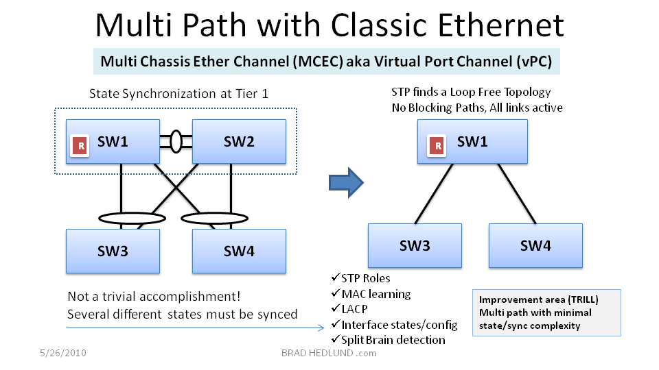
As shown in Figure 5 above, Switch 1 and Switch 2 form a special peering relationship with each other that allows them to be viewed as single switch in the topology, rather than two separate switches. This significant accomplishment allows Switch 3 and Switch 4 to form a single logical link with a single standard Etherchannel to both Switch 1 & 2. STP treats Switch 1 & 2 as a single node on the network, and as a result finds a loop free topology from the start, and no links need to be blocked, all links are active. Virtual Port Channels is a popular design choice today for maximizing bandwidth in new data center network deployments and redesigns.
Accomplishing MCEC or vPC capabilities is not a trivial task. A significant engineering effort is required. For MCEC implementations to behave properly you must engineer lock step synchronization of several different roles and states on each peer switch (Switch 1 & 2). You need to make sure MAC learning is synchronized, any MAC’s learned on Switch 1 must be made known to Switch 2. You need to make sure the interface states (up/down) are synced and the interface configurations are identical. You also need to determine which switch will process STP messages on behalf of the other. And to top it all off, most importantly, you need to have a robust split brain failure detection and determine how each switch will react and assume or relinquish the aforementioned roles and state. All of these different synchronization elements and split brain detection can lead to a complex matrix of failure scenarios that the switch maker must test and insure software stability.
The significant engineering effort of MCEC is for the simple purpose of providing STP a multi path loop free topology so that no links will be blocked. Will it be possible to build a multi path loop free topology without all of the system complexity of MCEC? The answer is, Yes, this is an enhancement in TRILL.
Scaling the next generation Data Center with Classic Ethernet
Now lets switch gears to scaling a pervasive Layer 2 data center fabric. Lets start by looking at the scaling options for Tier 1 (the Aggregation layer). First of all, why would you want to scale Tier 1 anyway? Well, the more capacity you can have available at Tier 1 means more Tier 2 (Server Access Layer) switches that can exist in the layer 2 domain. Furthermore, the more ports you have at Tier 1 means more aggregate bandwidth you can deliver to a Tier 2 switch. Therefore, the ability to efficiently scale Tier 1 is critical to the overall scaling of size and bandwidth to the server environment.

One interesting approach to scaling Tier 1 is to simply scale out by adding more switches horizontally across the Tier. This makes sense for a number of reasons. First of all, if you can connect the Tier 2 switch to an array of switches at Tier 1 you gain the advantage of spreading out risk, much like a RAID array of hard disk drives. For example, when a Tier 2 switch connects to (4) Tier 1 switches, a single uplink or Tier 1 switch failure would result in a 25% loss of available bandwidth, compared to a more significant 50% loss when there are just (2) Tier 1 switches. Second, if you can easily add more Tier 1 switches as you grow, the density of the Tier 1 switch becomes less of a factor in achieving the overall scale you need. For example, when you have the flexibility to eventually grow Tier 1 to (8) or even (16) switches, rather than only being limited to (2), you can achieve respectable scale with with an array of smaller low cost Tier 1 switches, or mind boggling scale with a wide array of larger modular switches.
Sounds great! Right? But before we start the high fives, how does scaling out Tier 1 work with the Classic Ethernet network relying on Spanning Tree Protocol for loop prevention? Well, it doesn’t… :-(

In Figure 6 above, I have attempted to scale out Tier 1 in a Classic Ethernet network. I have added Switches 5 & 6 to Tier 1 and linked my Tier 2 switches to the (4) switch array at Tier 1. Unfortunately though, the only thing I was able to accomplish was creating more loops that must be blocked by Spanning Tree Protocol. In order to maintain a loop free topology for flooded traffic (broadcasts & unknown unicast), all of the extra links I added from Tier 2 to Tier 1 have been disabled by STP, which if you remember punishes all traffic including the Known Unicast and Multicast traffic. What was the point? This was a futile exercise.
It is for this very reason why having more than (2) Tier 1 switches has never made any sense with Classic Ethernet. This long standing rigid design constraint has led the density of the Tier 1 switch being a very import criteria to achieving large scale and bandwidth. “How many ports can I shove in one box?” To achieve even respectable density in a modern data center requires a pair of large modular switches positioned in Tier 1, from which you can add modules as you grow. Once the module slots are filled you have hit your scalability wall, adding more Tier 1 switches is not a viable option.
Alright, so if loop prevention with Spanning Tree Protocol is the problem to achieving scale in Classic Ethernet, why not scale out Tier 1 with a design that does not create a looped topology to begin with? Such as with Multi Chassis EtherChannel (MCEC)? A great idea! Right? Well, maybe not…

In Figure 7 above, I have attempted to scale out Tier 1 with (4) switches all jointly participating in a Multi Chassis Etherchannel peering relationship. (First of all, this is a fictitious design, as no switch vendor has engineered this, not even Cisco. But lets just imagine for a second…) The plan here is to allow each Tier 2 switch to connect to all (4) Tier 1 switches with a single logical Port Channel, thus creating a loop free topology at the onset so Spanning Tree will not block any links. If I can already have (2) switches configured for MCEC peering, why not (4)? Heck, why stop at (4), why not (16)? The problem here of course is extreme complexity. Remember that accomplishing MCEC between just (2) switches is a significant engineering accomplishment. There are many states, roles, and Layer 2 / Layer 3 interactions that must be synchronized and orchestrated for the system to behave properly. On top of that, you must be able to quickly detect and correctly react to split brain failure scenarios. Once the MCEC domain is increased from (2) switches to just (4), you have increased the engineering complexity by an order of magnitude. As a testament to the engineering complexity of MCEC, consider that Cisco is the only major switch vendor to successfully engineer and support MCEC with (2) fully featured Layer2/Layer3 switches. And NO switch vendor, not a single one, has successfully engineered, sold, and supports a (4) switch MCEC cluster. Some switch vendors are hinting at such capabilities as a possible future roadmap in their data sheets. All I have to say about that is … Good Luck!
Is it possible to scale out Tier 1 with (4), (8), or even (16) switches in a loop free design with a lot less engineering complexity? The answer is, Yes! This is an enhancement in TRILL.
Another approach worth discussing is the complete removal of Layer 2 switching and replacing it with Layer 3 IP routing. By removing Layer 2 switching and replacing it with Layer 3 routing the switches behave more like routers with load balancing on multiple paths and no Spanning Tree blocking links. This also allows for scaling out each Tier without any of the Layer 2 challenges in Classic Ethernet as we have been discussing thus far. Sounds pretty good, right? Well, not so fast…
How do you provide pervasive Layer 2 services over a network of Layer 3 IP routing? The IP cloud formed by the Tier 1 & 2 switches would be used to create an MPLS cloud and deploy services such as VPLS (Virtual Private LAN Services) providing virtual Layer 2 circuits (pseudo wires) over the Layer 3 cloud. After a full mesh of VPLS pseudo wires has been configured between all Tier 2 switches you can begin to provide Layer 2 connectivity from any Tier 2 switch to another. Sound complicated? That’s because it is!

In Figure 8 above, the data center network has been setup as a VPLS-over-MPLS-over-IP cloud. Once that foundation is in place, I need to configure a full mesh of Layer 2 VPLS pseudo wires between all Tier 2 switches. How many pseudo wires do you need to configure? You can use this formula where N equals the number of Tier 2 switches: N * (N-1) / 2. And, for each new Tier 2 switch you add you will need to go back to every other Tier 2 switch and configure a new set of pseudo wires to the newly added switch. Not exactly Plug & Play, is it?
Rather than replacing Layer 2 with Layer 3, and then trying to overlay Layer 2 services over the Layer 3 … wouldn’t it be better to simply evolve Plug & Play Layer 2 switching with more Layer 3 like forwarding characteristics? This is exactly the idea behind TRILL.
Now lets finish up with a look at how Tier 2 scales under Classic Ethernet. Remember from earlier that having any more than (2) switches at Tier 1 makes no sense in Classic Ethernet, thanks to flooding loops and Spanning Tree. Because of this (2) switch design constraint the density potential of the Tier 1 switch you choose becomes a key factor in determining the scalability of network.
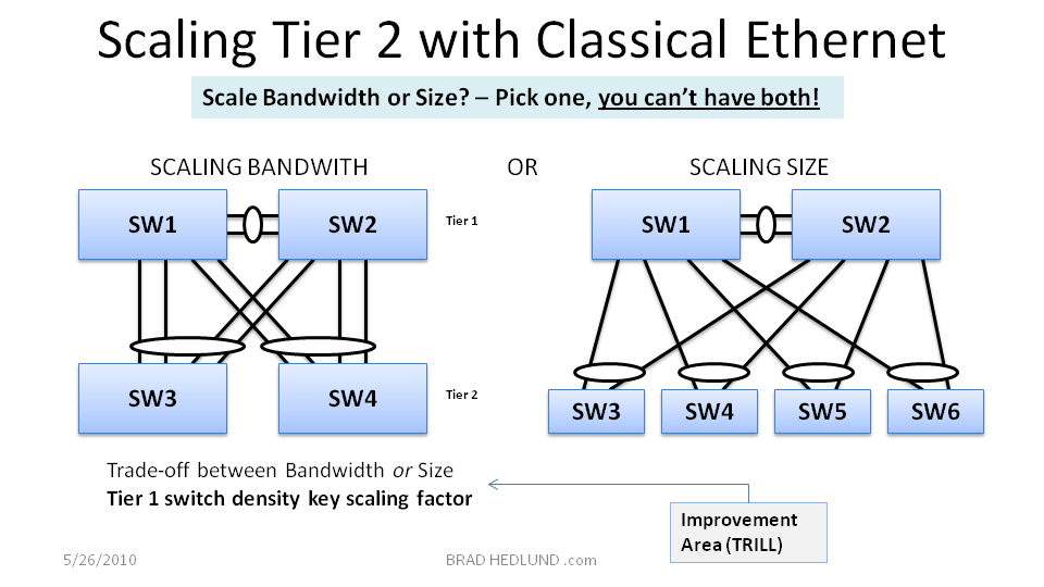
In Figure 9 above, because Tier 1 cannot have anymore than (2) switches there will always be a clear trade off between scaling bandwidth or scaling size. If I choose to give more bandwidth to Tier 2 it means less available capacity for adding more Tier 2 switches. This is largely the result of not being able to scale out Tier 1 horizontally with Classic Ethernet. If the rigid (2) switch design constraint was removed from the equation you suddenly have a lot more flexibility in how you can scale, and the trade off between bandwidth or size becomes less of black and white matter. Gaining this valuable flexibility with the data center switching design is a key promise behind the evolution to TRILL.
The stage has been set for the next evolution of data center switching
The next generation dynamic data center needs to have tremendous design flexibility to build highly scalable, agile, and robust Layer 2 domains. To get there, classic Ethernet switching as we know it today needs to evolve in the data center. The most successful solutions will be those that address many of the challenges facing the data center today, not just bandwidth.
What are the challenges that should be addressed?
- Plug & Play simplicity
- MAC address scalability*
- a more efficient method of MAC learning*
-
a hierarchichal approach to Layer 2 forwarding*
- Minimal configuration requirements
- All links forwarding & load balancing - No Spanning Tree
- More bandwidth for all traffic types, including Multicast, not just Unicast*
- Fast convergence
- Layer 3 virtues of scalability and robustness with the Plug & Play simplicity of Layer 2
- Flexible and agile scaling out of either Tier 1, or Tier 2.
- Configuration simplicity for automation with open API’s.
OK. Remember the goal here was to “set the stage” with a basis level understanding of why classic Ethernet switching needs to evolve for the next generation data centers. Please stay tuned for further detailed discussions on data center switching and TRILL.
RSS Feed: http://www.bradhedlund.com/feed/
Future topics may include:
-
TRILL technical deep dives
- Conversation based MAC learning
- Configuration examples
-
Design examples
- How and where does FCoE and Unified Fabric fit into this picture?
- Industry news & analysis
- Suggestions?
Presentation Download
I’m not sure who’s crazier: You (for reading this entire post without falling asleep)? Or Me (for writing such a long post)? Anyway, I have a reward for your time and attention! You get to download the presentation I developed for this post. There are some extra slides that provide a sneek peak into my next posts, an Introduction to TRILL.
PDF: http://internetworkexpert.s3.amazonaws.com/2010/trill1/TRILL-intro-part1.pdf
Original Power Point with Animations: Please ask your Cisco representative
Special Thanks to my colleagues at Cisco: Marty Ma, and Francois Tallet. Both of whom are deeply involved with Cisco’s implementation of TRILL* and took precious time to provide me with a 1:1 education about some of the topics covered here.
Disclosure: The author (Brad Hedlund) is an employee of Cisco Systems, Inc. which plans to have TRILL based solutions embedded into the companies data center switching product line.
Disclaimer: The views and opinions expressed are solely those of the author as a private individual and do not necessarily represent those of the authors employer, Cisco Systems, Inc. The author is not an official media spokesperson for Cisco Systems, Inc.